

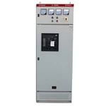
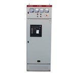

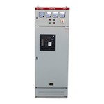
HV Metal-Clad Switchgear Cabinet
Product Overview
This metal-clad switchgear is an indoor medium- and high-voltage power distribution system designed for three-phase AC networks operating at 3.6 kV to 40.5 kV and 50/60 Hz. It is engineered for incoming power reception, feeder distribution, circuit protection, busbar sectionalizing, and electrical isolation in utility substations and industrial power distribution systems.
The switchgear utilizes a compartmentalized metal enclosure featuring physically isolated compartments for the circuit breaker, main busbars, cable connections, and low-voltage control equipment. This structured layout is designed to restrict fault propagation, support routine maintenance, and isolate functional units within the switchgear lineup.
Depending on the specified voltage class, current rating, protection philosophy, and project schematics, the equipment is supplied with withdrawable vacuum circuit breakers, current and voltage transformers, earthing switches, surge arresters, protection relays, metering equipment, and customized secondary control wiring.


Construction & Configuration
The switchgear structural enclosure is assembled from formed, CNC laser-cut, and bent coated steel sheet components. Bolted assembly techniques allow individual structural panels to be fabricated with high dimensional precision, inspected, transported, and installed as a rigid switchgear lineup.
The primary equipment is segregated into four distinct functional compartments:
Circuit Breaker Compartment
Houses the withdrawable vacuum circuit breaker (VCB) mounted on a precision-guided truck mechanism, providing defined service, test, and disconnected positions. Automatic metallic shutters cover primary circuit interfaces when the breaker truck is racked out, restricting access to energized components.
Busbar Compartment
Accommodates the main busbar system and associated insulated supports. Copper busbars can be supplied with protective insulation or specialized joint treatments according to the voltage class and electrical design requirements.

Cable Compartment
Provides internal space for incoming or outgoing cable terminations and primary equipment, including current transformers, voltage transformers, earthing switches, surge arresters, and cable supports.
Low-Voltage Control Compartment
Physically isolated from all high-voltage zones, this compartment houses secondary control, protection, metering, communication interfaces, terminal blocks, and auxiliary control wiring configured to approved schematics.
Key Features
Compartmentalized Metal Construction: Enclosure separates the circuit breaker, busbar, cable, and low-voltage sections into independent functional areas to support controlled access and maintenance safety.
Withdrawable Vacuum Circuit Breaker: Enables defined operating states (service, test, and disconnected positions) with mechanical endurance ratings matched to system requirements.
Mechanical Interlocking: Incorporates interlocking functions to govern critical operating sequences, preventing unauthorized circuit breaker racking, mismatched switching operations, and unsafe access.
Pressure Relief Arrangement: High-voltage compartments feature engineered pressure-relief structures designed to provide upward exhaust channels for ionized gases during an internal arcing event.
Modular Lineup Configuration: Individual vertical panels couple seamlessly side by side to form complete incoming, outgoing, transformer, and bus-section lineups tailored to site dimensions and shipping limits.
Integrated Earthing Switch: High-capacity earthing switch installed in the cable or primary compartment, rated for making currents corresponding to prospective short-circuit levels.
Technical Specifications
|
Parameter |
Specification Range |
Reference / Notes |
|
Rated Voltage |
3.6 kV to 40.5 kV |
IEC 62271-1 / IEC 62271-200 |
|
Rated Frequency |
50 / 60 Hz |
According to project requirement |
|
Rated Normal Current - Busbar |
1250 A to 4000 A |
Configuration dependent |
|
Rated Normal Current - Feeder |
630 A to 3150 A |
Configuration dependent |
|
Short-Time Withstand Current |
25, 31.5, 40, 50 kA (up to 3 s) |
According to selected configuration |
|
Peak Withstand Current |
Up to 125 kA |
Dependent on short-time rating |
|
Circuit Breaker |
Withdrawable vacuum circuit breaker |
Selected per system requirements |
|
Power-Frequency Withstand Voltage |
Per rated voltage class |
IEC 62271-1 / applicable configuration |
|
Lightning Impulse Withstand Voltage |
Per rated voltage class |
IEC 62271-1 / applicable configuration |
|
Internal Arc Classification |
Available per tested configuration |
IEC 62271-200 |
|
Service Continuity Classification |
Configuration dependent (e.g., LSC2B) |
IEC 62271-200 |
|
Partition Class |
Metallic partitions (PM) |
IEC 62271-200 |
|
Protection Degree |
IP31 / IP42 / specified class |
IEC 60529 |
|
Busbar Material |
High-conductivity electrolytic copper |
Material/treatment project dependent |
|
Installation |
Indoor |
Site conditions to be confirmed |
|
Control & Protection |
Customized per approved schematics |
Relay, metering, communication options |
Applications
Utility & Industrial Substations: Incoming power reception, feeder distribution, transformer feeding, bus sectionalizing, and electrical isolation within medium-voltage nodes.
Industrial Power Distribution: Heavy manufacturing plants, processing facilities, and infrastructure projects requiring reliable continuous current ratings and fault clearance.
Renewable Energy Power Collection: Medium-voltage collection and distribution hubs for utility-scale solar and wind power generation plants.
Critical Power Infrastructure: Facilities requiring defined feeder protection, circuit isolation, selective fault management, and high service continuity.
Manufacturing & Quality Control
Production Workflow
Sheet Metal Processing: Steel sheets are processed via CNC laser cutting, punching, and bending to maintain tight dimensional tolerances defined by engineering drawings.
Busbar Fabrication: Electrolytic copper busbars are cut, punched, bent, and surface-treated (silver/tin plating) to ensure low contact resistance and stable thermal performance.
Mechanical Assembly: Cabinet sections and subassemblies are built using dedicated assembly fixtures to guarantee alignment of breaker trucks, shutter mechanisms, and interlocking rods.
Secondary Wiring & Integration: Control, protection, metering, and auxiliary circuits are wired according to approved schematics, with numerical ferrules and continuous continuity testing.
mill CNC machine
Power-Frequency Withstand Test: Verification of primary insulation performance under high-voltage test conditions.
Main Circuit Resistance Measurement: Micro-ohmmeter verification of primary circuit paths and electrical joint connections.
Mechanical Operation Test: Functional verification of circuit breaker racking, truck travel, automatic shutters, and mechanical interlocking sequences.
Secondary Circuit Verification: Continuity, functional checks, and wiring validation of control, indication, and protection circuits.
Protection & Metering Verification: Relay and metering calibration checks aligned with approved control schemes.
Visual & Dimensional Inspection: Final verification of enclosure dimensions, component placement, labeling, and overall assembly against approved drawings.
Customization & Project Support
Engineering Submittals:
Complete provision of general arrangement drawings, single-line diagrams, secondary wiring diagrams, terminal lists, 3D models, and foundation loading layouts upon order confirmation.
Custom Protection Schemes:
Low-voltage control compartments engineered to integrate client-specified protection relays, meters, and communication protocols.
Site Integration Support:
Technical guidance for positioning, busbar bridging across shipping splits, and high-voltage cable termination procedures.
FAQ